Circular Microstrip Patch Antenna Calculator
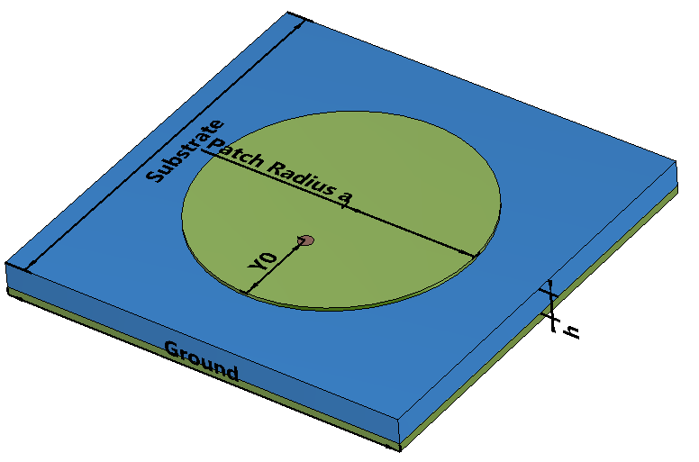
The dimensions of circular patch antenna is calculated for the dominant \(TM_{110}^{z} \) mode.
Formula
\(a=\frac{F}{\left \{ 1+\frac{2h}{\pi\epsilon_rF}\left [ ln(\frac{\pi F}{2h}+1.7726 ) \right ] \right \}^\frac{1}{2}}\)
\(F= \frac{8.791e^9}{f_r\sqrt{\epsilon_r}}\)
\(a_e=a{\left \{ 1+\frac{2h}{\pi a \epsilon_r}\left [ ln(\frac{\pi a}{2h}+1.7726) \right ] \right \}^\frac{1}{2}}\)
\(D_{0}=\frac{(k_{0}a_{e})^{2}}{120G_{rad}}\)
\(G_{rad}=\frac{(k_{0}a_{e})^{2}}{480}\int_{0}^{\pi/2}\left [J_{02}^{'2}+cos^{2}\theta J_{02}^{2} \right ]sin \theta d \theta\)
\(J_{02}^{'}=J_{0} (k_{0}a_{e}sin \theta)-J_{2} (k_{0}a_{e}sin \theta)\)
| Where: |
| \(f_r \) = Frequency |
| \(\epsilon_{r}\) = Substrate Relative Permittivity |
| \(h\) = Substrate Height |
| \(a \) = Physical Radius of Patch |
| \(a_e \) = Effective Radius |
| \(D_{0} \)= Directivity of Patch Antenna |
| \(G_{rad} \) = Conductance across the gap between the patch and the ground plane |
| \(J_{0}\) = Bessel function of the first kind of order 0 |
| \(J_{2}\) = Bessel function of the first kind of order 2 |
Reference:
- [1] Balanis, C.A. (2016). Antenna Theory: Analysis and Design. 4th ed. Hoboken, New Jersey Wiley, pp.814–823. Chapter 14.3 Circular Patch.